Home |
Biographical Sketch |
Building Statistics |
Thesis Abstract |
Technical Assignments |
Thesis Research |
Thesis Proposal |
Presentation |
Final Report |
Reflection |
Senior Thesis e-Studio |
Building Statistics Part 2 |
|
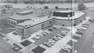
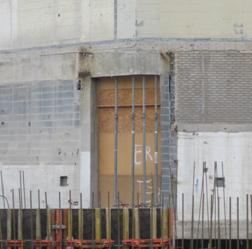
CONSTRUCTION Demolition: The existing Arena Stage consists of two theatres: the Fichandler Theatre, built in 1960, and the Kreeger Theatre, later added in 1971. Both of the structures are concrete block with steel frame and are two stories above grade with a below grade basement. Portions of the Kreeger theatre, administrative offices, and the connecting building were razed prior to the beginning of the new construction. Due to the age of the existing facility, multiple items containing hazardous materials were identified throughout the building. Included were asbestos, lead paint, potential sources of poly-chlorinated biphenyl (PCBs), and a 55 gallon drum of HVAC water treatment chemicals. Asbestos was found in pipe fitting insulation, mastic, duct insulation, ceiling tiles, floor tiles, spray-on insulation, and transite asbestos board. Luckily, most of these items were classified as being in fair to good, non-friable condition. Possible PCB containing sources were the old fluorescent light ballasts, power transformers, and hydraulic fluid from the elevator. During demolition and during renovation, the building had containment areas for asbestos abatement. Preventive measures were taken while removing the contaminated materials from the building and also during their disposal. With the exception of some salvageable masonry, little to no recycling of materials was done during the demolition of the original Arena Stage.
Support of Excavation: Since the original structures of the Fichandler and the Kreeger theatres are remaining for renovation, proper support was required during excavation. A temporary earth retention system was installed using underpinning and sheeting and shoring. Materials include WF and HP steel piles, low carbon steel lagging studs, tieback tendons, 3” thick hardwood for lagging, tieback grout, and pile shaft backfill. The underpinning was performed through installation of drilled or driven cantilevered, braced, and tieback HP solider bearing piles. Approach pits and underpinning pits were dug and then excavated with interpier (beam/wale) lagging between pits to the tieback elevation. The Fichandler has underpinning on the interior of three perimeter walls and the Kreeger has it in areas where support walls were removed. Although the system is primarily temporary, a several underpinning locations were permanent. Sheeting and shoring was also used. After the piles were laid out, they were driven/drilled. Excavation was done and lagging was installed to one foot below each tie or brace elevation. Once the tiebacks were installed and tested, excavation was continued to the subgrade and if required, braces were installed. Cantilevered sheeting was installed on the Main Avenue side of the Kreeger. Above-ground shoring was installed in necessary locations around the Kreeger as well. Tiedback sheeting is on the interior 6th Street wall of the Fichandler. Additional sheeting surrounds the majority of the site around the new building footprint. Another necessary excavation support was for an existing 8” water line along 6th Street SW. The system is free draining with no allowance for hydrostatic pressures. Based on the groundwater reports, sump pumps were provided on the parking level as the foundation and underslab drainage systems. It was installed prior to excavation to eliminate all hydrostatic pressures against the sheeting system and to lower and maintain the water table below design subgrade.
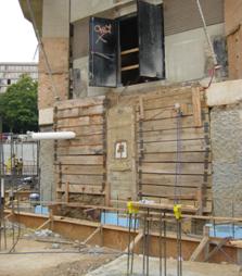
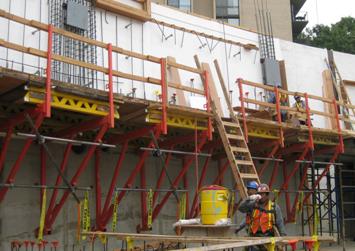
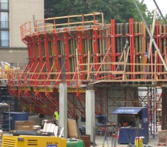
ELECTRICAL & LIGHTING Arena Stage’s electrical service is supplied by Pepco, a regulated electric utility that provides transmission and distribution services to most of Washington, DC. The main feed is brought into the building and stepped down by a Pepco transformer to a 3Φ, 4 wire, 277/480V, 3000A bus. The size is adjusted throughout the building with 8 Dry Type Transformers. Emergency power is supplied by one 275kW/344kVA separately derived fixed generator system. The generator runs on a 1800 rpm-speed diesel engine that powers 3 emergency multi-duct conduit (EMDC) systems. It was sized to carry the loads of the fire pump, mechanical system, snow melting, lighting, and uninterrupted power supply. The stage lighting control system includes multiple 20A high-density solid-state dimmers. They are controlled by an electronic memory in the control room so that intensity levels and fade times can be stored and recalled in the system. House lighting control systems also include high-density, solid-state dimmers controlled by electronic memory. Tour lights, cleaning lights, and emergency lights are all a part of this system. MECHANICAL The HVAC system consists of central boiler and chiller plants and central outdoor air distribution to multiple constant volume air handling systems for the acoustically sensitive spaces and other large spaces. Fan powered induction systems are used for smaller zone control of the back of house areas. The mechanical classification is a 4-pipe, air-water fan coil system. 4 gas-fired boilers are located in the boiler room located on level 49.5’, served by dedicated constant flow primary heating hot water pumps. 2 electric centrifugal chillers are located in the chiller room on level 0.0’ of the Fichandler and served by 3 condenser pumps. 2 single cell counterflow centrifugal fan type cooling towers are located on the terrace of level 43.0’. There are 2, 100% outside air handling units (OHUs). One is located on the roof of the Cradle and the other is in the Kreeger mechanical room. The Kreeger and the Fichandler are each served by 2 separate constant volume air handling units (AHUs), one for the seating area and one for the stage. Due to the smaller size of the black box theatre, the Cradle is only being served by one AHU. 13 other AHUs serve the lobby, mall, switchgear rooms, and other administrative locations. The air handling units, whether constant or variable, range from 3,000 to 43,100 cfm. Fan powered induction units (FPIUs) provide individual zone temperature control and ventilation to multiple areas in the back of house. Horizontal and vertical fan coil units (FCUs) are provided for unoccupied areas that require cooling/heating. A total of 31 FCUs ranging from 220 to 2,900 cfm are scattered throughout the complex. The primary method for controlling and monitoring the mechanical system is a state of the art control system with stand alone digital controllers. STRUCTURAL Cast-in-Place Concrete: A majority of the new work on Arena Stage utilizes cast-in-place (CIP) concrete. While only a minimal amount is used the Fichandler and the Kreeger, the majority is used on the underground parking garage and the Cradle Theatre. The horizontal pours, along with some vertical work, are being placed using standard formwork with a traditional scaffold frame and stringer/joist assembly. Due to the nestled, ellipse-shaped walls of the Cradle, the vertical formwork is a much more complex system. To achieve this architectural element, Clark Concrete is using a PERI Formwork System. It consists of a CB 240 climbing platform and RUNDFLEX circular wall formwork. The CB 240 system uses strongbacks which are connected to brackets via a carriage that has a rack and an adjustable brace. 2.40 meter wide pre-fabricated decking is then set level with the brackets and the carriage.
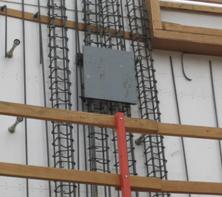
The RUNDFLEX circular wall formwork is a flexible solution to the shape and slope of the Cradle walls. There are over 2,000 templates circulating the project in order to successfully place the concrete walls. The templates are placed on the back of the RUNDFLEX formwork, which is then adjusted by either tightening or loosening the joints on the back of it. Once the template is matched, the walls are prepared for pouring in 10’ lifts. Since the walls sit on a 4 degree slope, gaps begin to appear in between the runs of formwork. Although it is only about 1” at the bottom of the wall, it is estimated that it will be as large as 17” once the lift is complete. In order to close this gap, custom cut fillers are wedged between the formwork to create a smooth face and consistent horizontal wall joint.
Structural Steel: The structural steel used on Arena Stage is primarily located in the ceiling and the cantilever roof. A series of wide flange girders and beams make up the ceiling system, which carry the loads of the 45’ glass façade and transfer them to the PSL timber columns (described in the Curtain Wall section) along the building perimeter. For acoustical reasons, many of the trusses are bearing on isolation pads on steel brackets. This allows for separation of the decks of the composite floor slabs from floor to floor.
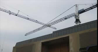
The cantilever roof is a matrix of diamond oriented bracing trusses and hollow structural section (HSS) beams. HSS beams make up the overhang of the roof that is supported by stainless steel tension cables. Scalloped cladding covers the overhang and gives the building a sleek finish. Due to the intense structural system of the roof, a finalized steel schedule is not yet available. Two tower cranes are available on Arena Stage’s site. The first has a 245' jib length and a 6,600 pound weight capacity. The second tower crane has a 180' jib length and a 6,280 pound weight capacity. They are located in areas of the site where multiple trades can take advantage of their use. One is on the northwest tip of the site and the other is to the southeast of the Fichandler. The use of both cranes makes is possible to reach around the entire site.
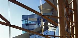
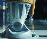
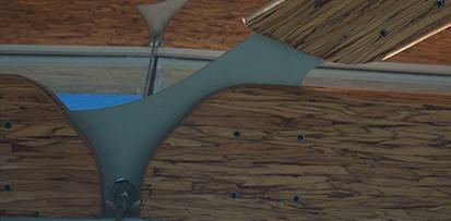
FIRE PROTECTION The fire suppression system implemented in Arena Stage consists of both a wet and dry sprinkler system. It is a combined standpipe and sprinkler system; the sprinkler system is supplied from the standpipe system. Automatic wet-type, Class I standpipe system has an open water supply valve with a maintained pressure. It is capable of supplying water demand is a short amount of time. ADDITIONAL BUILDING SYSTEMS Elevators: There are (3) hydraulic elevators servicing Arena Stage. The first is a 2500 lb. twin jack holeless hydraulic passenger elevator. It serves 2 floors of the main lobby and foyer in the Cradle Theatre area with both front and rear car openings. The second also has a 2500 lb. capacity, but is a conventional holed hydraulic passenger elevator serving the Kreeger bar and administration offices. Having 5 stops and front and rear openings, this elevator will be utilized the most. The third is a conventional holed hydraulic freight elevator serving the back of house. Operating with 6 stops, 8 openings, and a 9' cab height, this 10,000 lb. capacity elevator will be used for moving the majority of the stage equipment and other large shipments. Curtain Wall: The 45’ tall curtain wall is one of the main design features of Arena Stage. The glazing is on an inverted 4 degree slope and the wall is a serpentine comprised of multiple radii. It is sectioned off into 12’×7/8” insulated glass frames which weigh approximately 850 pounds per unit. They are hung from the ceiling by stainless steel cables, supporting the dead load of the glass. Since the glass units are so heavy, the system was designed to be installed from the top down. This was done in order to load the cables that are anticipated to stretch ½” as a result of the weight. The cables are then supported by wide flange beams located in the ceiling above the lobby. Huge parallel strand lumber (PSL) timber columns, designed by StructureCraft Inc., back up the façade and support the entire system. The ellipse-shaped, solid columns range from 48’ to 58’ in length and are approximately 30” in diameter. Sitting 3’ off of the glass, they are placed 36’ on center along the perimeter of the building and run continuous up to the roof. Sprouting off the columns are support arms that support the horizontal muntins which carry the lateral loads of the façade. These pieces are connected by an aluminum plate which is penetrated by the stainless steel support cables. The base of the columns is a cast ductile-iron mount that is bolted to the floor.
|
| User Note: While great efforts have been taken to provide accurate and complete information on the pages of CPEP,
please be aware that the information contained herewith is considered a work-in-progress for this thesis project.
Modifications and changes related to the original building designs and construction methodologies for this
senior thesis project are solely the interpretation of Joni Anderson. Changes and discrepancies in no way
imply that the original design contained errors or was flawed. Differing assumptions, code references, requirements,
and methodologies have been incorporated into this thesis project; therefore, investigation results may
vary from the original design. |